Expert Documentation
Most of you will never have to mess with this, though it may be useful if you are using iOLab in your studies of electrical engineering or computer science.
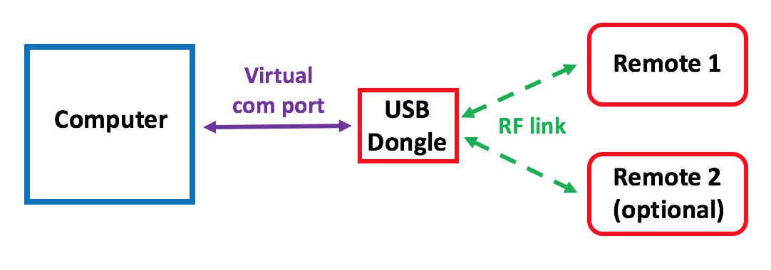
Your iOLab system is composed of one or two Remotes, a Dongle, and a computer running the iOLab application. The dongle communicates with the Remote(s) using a 2.4 GHz wireless link employing on a light-weight dedicated protocol, and the computer application communicates with the Dongle using a simple Virtual Com Port (RS232) serial protocol. The documents linked below describe this communication and the commands and functions understood by the system. You don't need the iOLab application to communicate with the DOngle and the Remote; as long as the virtual com port driver is enabled on your computer and have this documentation handy, you can talk to the devices using a simple terminal emulator.
iOLab_usb_interface_specs.pdf. This document describes the commands needed to communicate with the iOLab Dongle and your iOLab Remote.
iOLab_data_specs.pdf. This document describes the way that data is moved between the Dongle and Remote(s).
iOLab_remote_SCH.pdf. Schematics of Remote.
Expansion Boards
The connectors on top of the iOLab device, providing analog and digital I/O pins as well as power and ground, are designed to hold user-designed expansion boards. A board to give the iOLab device 9-lead ECG functionality currently exists and is documented below.
ECG_Summary.pdf. Brief summary of ECG Plug-in board project including some pictures.
ECG_schematic.pdf. Schematic of ECG Plug-in board.
ECG_Board_Specs.zip. Manufacturing details for ECG Plug-in board.
ECG_Publication.pdf. Clinical study using iOLab ECG system. The hardware used in this study was older and less capable than the hardware documented above.
Electrophysiology_using_iOLab.pdf. Describes a way to do a simple 1-lead ECG without the use of the ECG Plug-In (i.e. just using a couple of wires and clips).